RS660 IMU dampening Device

$180.00

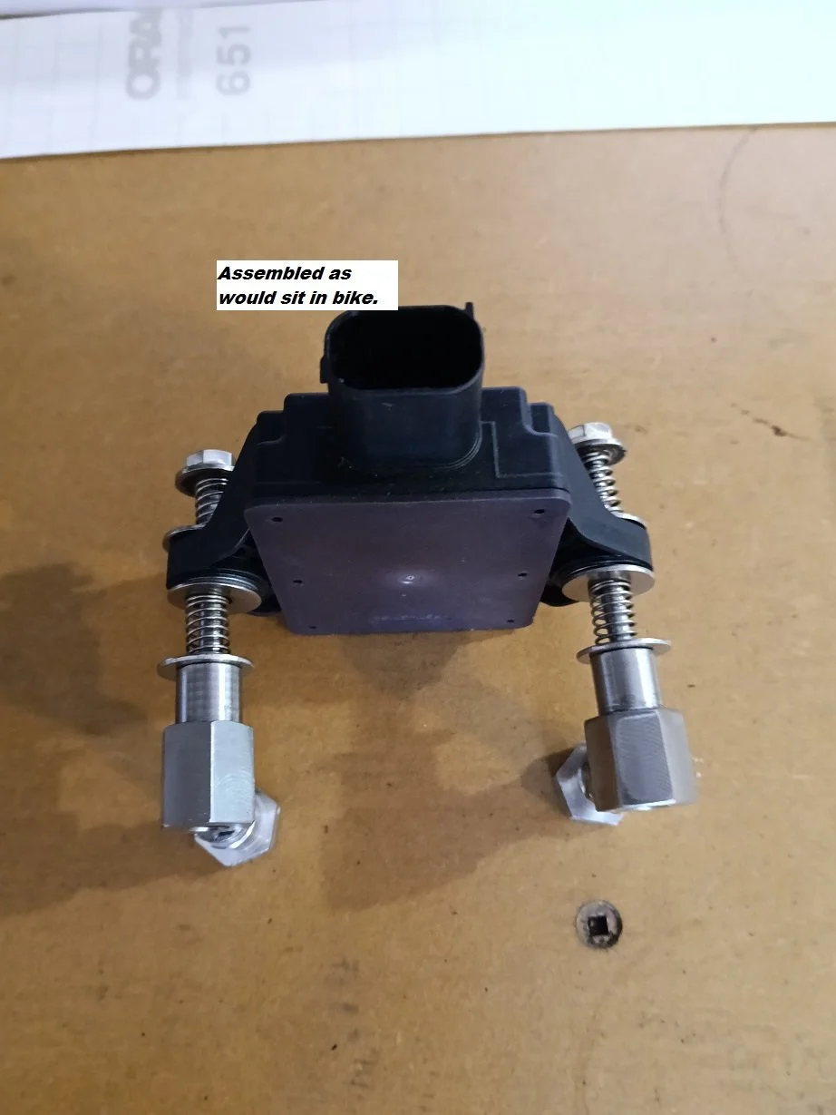
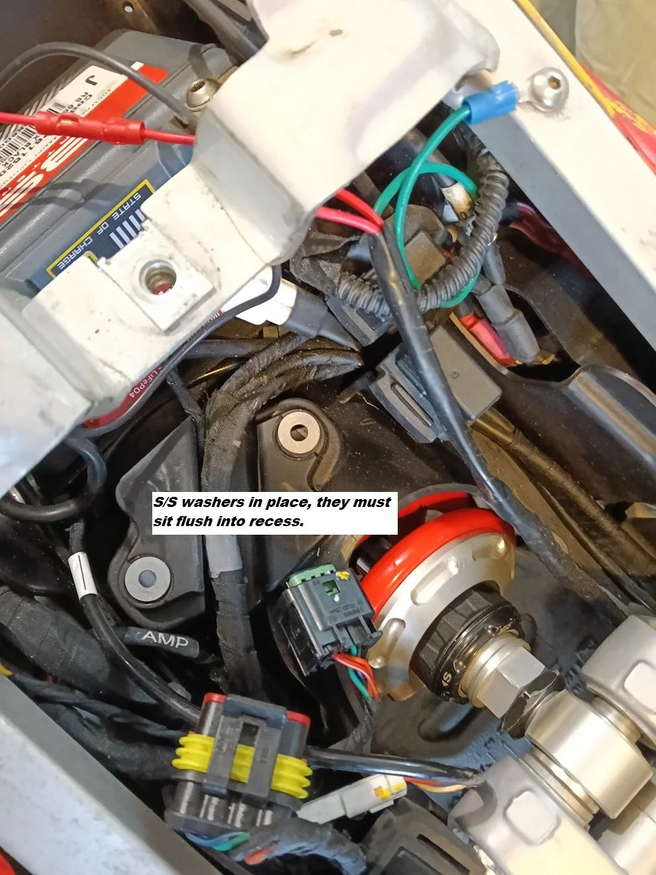
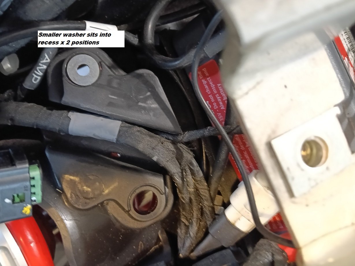
When you receive your dampener please notice the parts and there order. Should two washers be smaller in Diametre then these must fit into the recess on the Sub Frame moulding IMU side.Should all  washers (6 off) be the same size then there positions won’t matter except that they must be positioned under the springs. see photos.

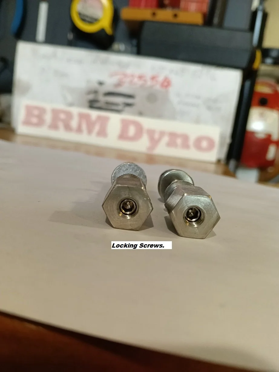
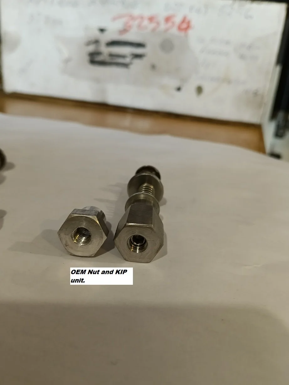
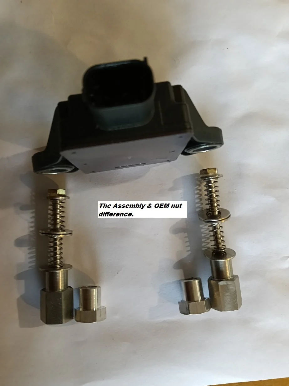
You should receive 2 shafts. 4 springs. 2 Nuts, 6 washers and 2 locking crub screws . The crub screw may be inside the nut.

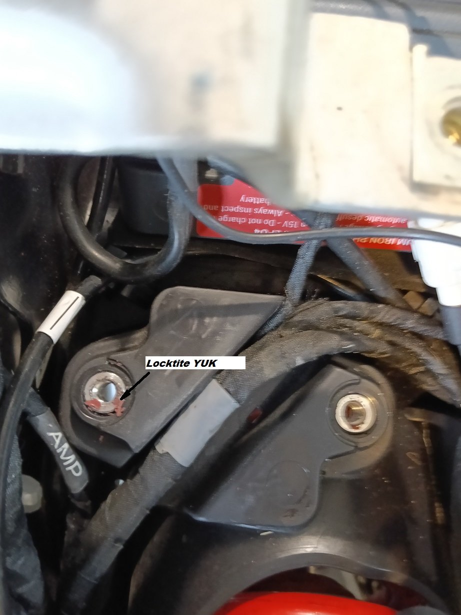
 After you have removed your RS660’s seat and fuel tank you will notice the IMU. When you proceed to remove the bolts be cautious as the special nuts are often loctited (OEM) to the 6mm bolts. We at KIP don’t like Loctite and hence the crub screws are used to lock our nuts in place. Not saying you can’t use Loctite but because they are Loctited you have trouble removing the nuts, using a heat gun (hair Drier) from the underside might help to break down the loctite but do not come in from the IMU side as excess heat could render the IMU useless. Our Nuts are made longer which enables you to put a socket (14mm) or spanner on the nut and tighten or loosen etc.  

Notice the crub screws, these are screwed in as far as they will go then the main shaft gets tightened to contact the crub screw and in doing so locks the system in place, avoiding the need for loctite.

The Crub screws can be adjusted out to give more spring tension on the IMU but the position of all the way in, (about 3-5mm below surface) works  without fault.

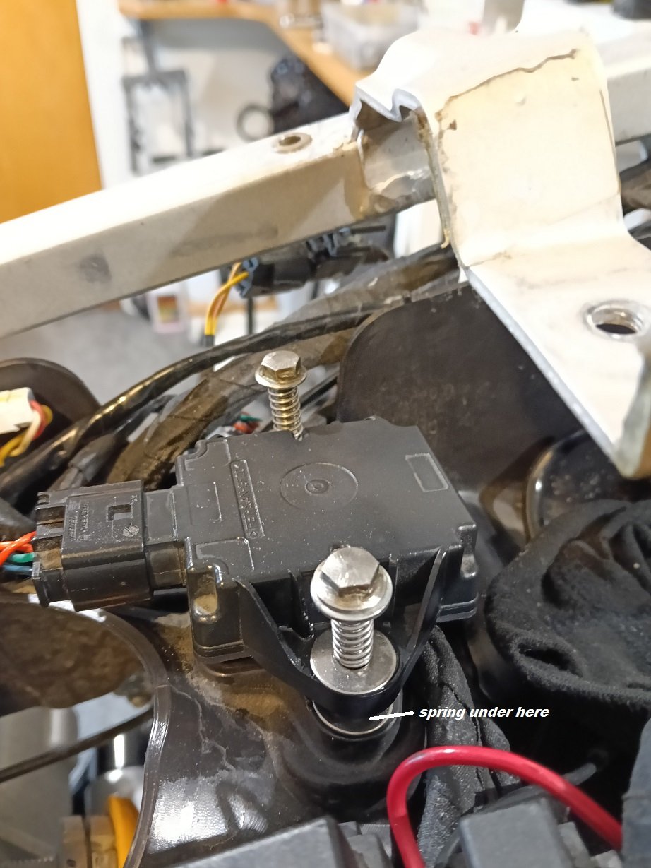
 The assembly,notice the spring position and washers, the washers are best with the flatter side facing the springs but this is not paramount. When assembled into your RS660 be sure that the IMU will float with just a little downward pressure.

Placing a small amount of grease around the unthreaded part of the shaft is recommended but again not essential. If you do add grease then only use enough to very lightly coat the shaft.

Once you have the system fitted, (It is not necessary to remove the Shock Absorber) be sure if not using loctite that the small crub screw is locked to the main shaft. 6 or 7 Nm  is ample…


When you receive your dampener please notice the parts and there order. Should two washers be smaller in Diametre then these must fit into the recess on the Sub Frame moulding IMU side.Should all  washers (6 off) be the same size then there positions won’t matter except that they must be positioned under the springs. see photos.

You should receive 2 shafts. 4 springs. 2 Nuts, 6 washers and 2 locking crub screws . The crub screw may be inside the nut.

 After you have removed your RS660’s seat and fuel tank you will notice the IMU. When you proceed to remove the bolts be cautious as the special nuts are often loctited (OEM) to the 6mm bolts. We at KIP don’t like Loctite and hence the crub screws are used to lock our nuts in place. Not saying you can’t use Loctite but because they are Loctited you have trouble removing the nuts, using a heat gun (hair Drier) from the underside might help to break down the loctite but do not come in from the IMU side as excess heat could render the IMU useless. Our Nuts are made longer which enables you to put a socket (14mm) or spanner on the nut and tighten or loosen etc.  

Notice the crub screws, these are screwed in as far as they will go then the main shaft gets tightened to contact the crub screw and in doing so locks the system in place, avoiding the need for loctite.

The Crub screws can be adjusted out to give more spring tension on the IMU but the position of all the way in, (about 3-5mm below surface) works  without fault.

 The assembly,notice the spring position and washers, the washers are best with the flatter side facing the springs but this is not paramount. When assembled into your RS660 be sure that the IMU will float with just a little downward pressure.

Placing a small amount of grease around the unthreaded part of the shaft is recommended but again not essential. If you do add grease then only use enough to very lightly coat the shaft.

Once you have the system fitted, (It is not necessary to remove the Shock Absorber) be sure if not using loctite that the small crub screw is locked to the main shaft. 6 or 7 Nm  is ample…


IMU (Inertial Measurement Unit) This unit has undergone extensive testing and is a result of many different designs from the IMU floating  on blocks or suspended on a frame with soft insertion rubber to crudely loosely mounting the IMU to sponge rubber and held in place with electrical ties.  To varying degrees all worked but until we tried this current device we couldn’t completely eliminate getting of the line without interruption.  When a wheelie was pulled the occurrence would happen as the bikes front wheel came back to the tarmac. Most of the testing has been down the road from our workshop and around the block as testing on the race track is not so simple and dangerous should a failure occur, however testing on the race track to date has so far been successful . To this end testing will always be ongoing.

The unit is not presently endorsed by our New Zealand motor cycling body, (MNZ) the organisation was approached but failed to show interest, it would be hoped that in the future they (MNZ) will endorse the unit. As a result fitting and using this unit is at your own risk and primarily for track or race use. Please be sure to give us feedback.  

 Often fault codes would display but more often than not the dash would light up like a Xmas tree. The symptoms are often ATC or ABS or AWC alarms with engine and ignition cuts. Often there would be no alarms. The primary cause seems to be vibrations when the race bike is leaned over or under strong acceleration.  Sensor box failure P1911 alarm is often generated.

However a further failure may be that the ECU and firmware is mounted directly behind the cylinders and as a result any overheating or higher engine temperature could create problems, being that electronic drivers have as there greatest enemy heat and these problems may show up as the mentioned alarms, P1911 etc and incorrectly diagnosed as IMU problems. Excess heat can alter impedance and modern day electronic communication can be effected. Whats the answer, not sure, perhaps remove the thermostat for better water flow, Remove any stone guards, keep the Air induction cowlings in place.